Building a Bridge Over the Buffalo Creek
Building a bridge over the Buffalo Creek using 3D-printed components.
Building a model railroad bridge over the Buffalo Creek was at the top of my to-do list when I decided to build this layout. Hopefully this will be a signature scene.
I started by shaping the landscape around the creek scene using foam and tape.
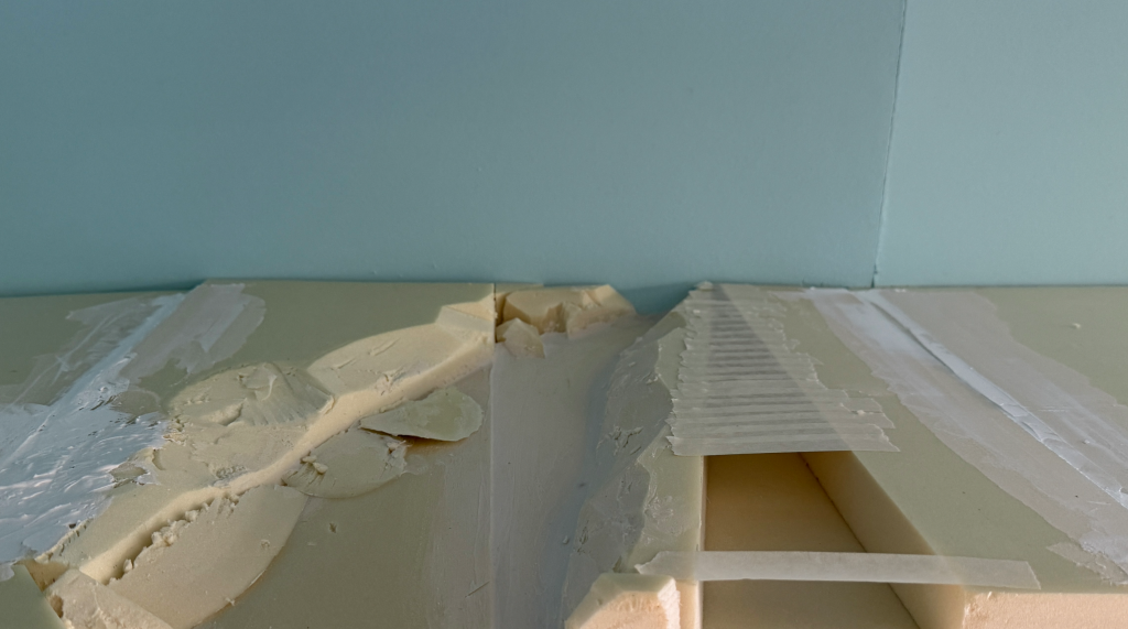
Then, I masked the backdrop and mixed some papier-mâché with brown acrylic paint to tone down the white color. Next, I started applying the papier-mâché to shape the terrain.
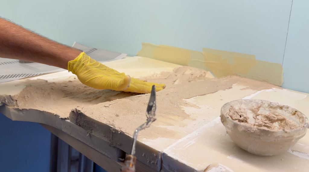
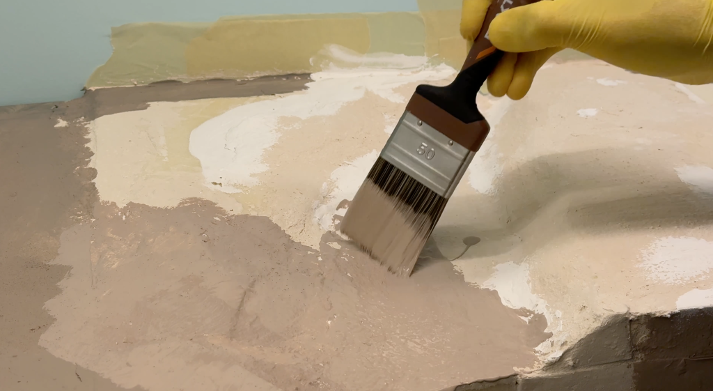
Then, I painted the whole scene with a tan base color.
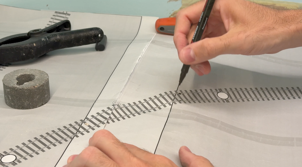
I marked the track position using the 1:1 scale paper track plan.
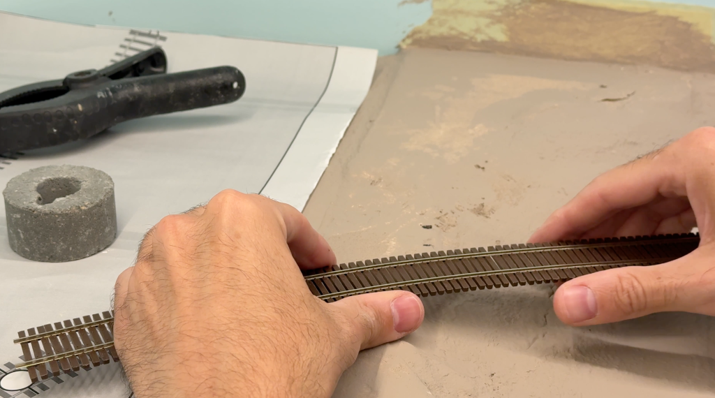
I’m going to use this Micro Engineering Code 70 bridge track.
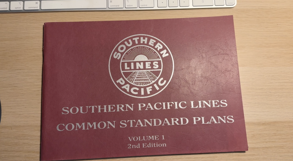
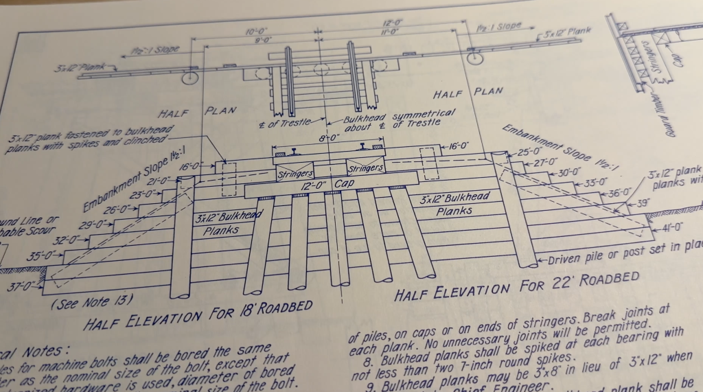
To find inspiration for drawing and 3D-printing my own trestle components, I used this Southern Pacific Common Standard Plan book.
Then, I shaped the terrain behind the abutments using scrap foam pieces and acrylic glue.
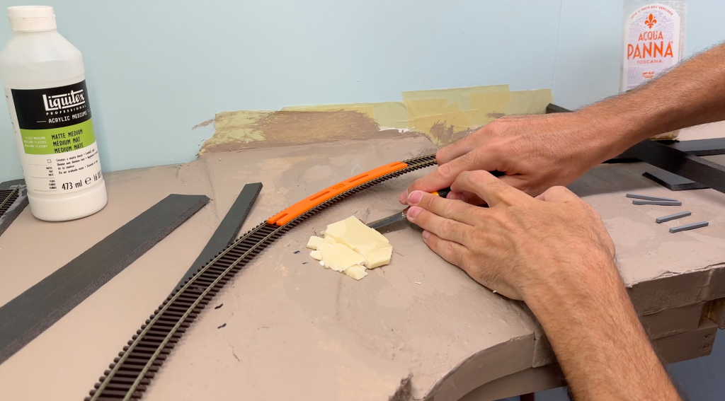
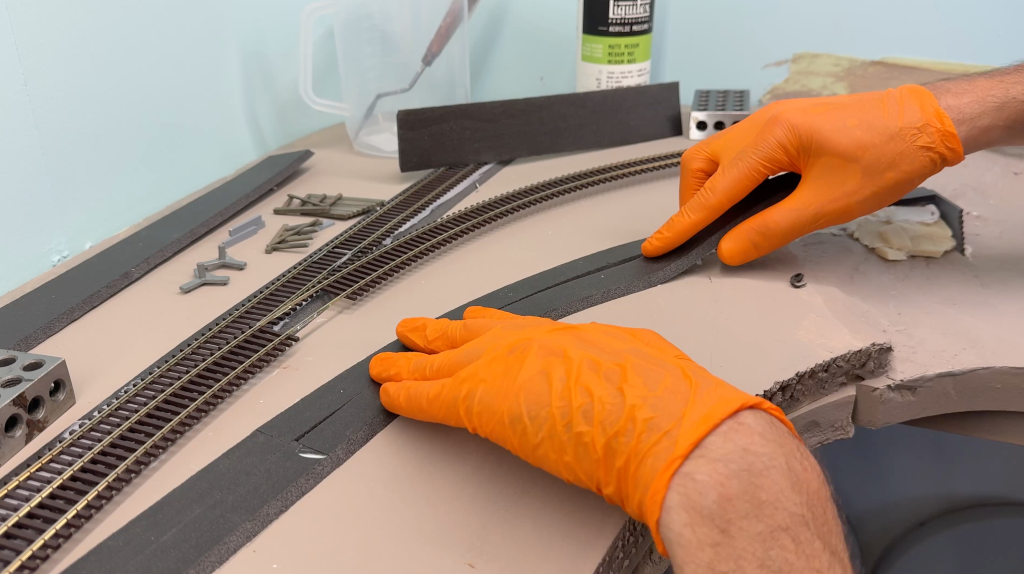
I glued down the roadbed, always making sure the track had the correct radius with my 3D-printed gauge.
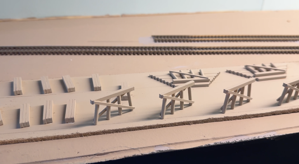
Building a Bridge Over the Buffalo Creek: assembling the trestle
Building a bridge over the Buffalo Creek with this 3D-printed version of the trestle, primed with a light, warm gray color.
To paint and weather the trestle, before assembly, I used undiluted Vallejo acrylic paint.
- Vallejo Concrete (71.131)
- Vallejo Dark Sea Grey (71.053)
- Vallejo Dark Olive Drab (71.316)
- Vallejo Stonewall Grey (72.749)
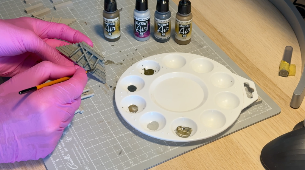
I deliberately mixed the paint randomly to create an old wood effect.
I ended up printing the trestle components with PETG because it’s sturdier than PLA. PLA breaks very easily, while PETG takes a lot more effort to break. Not that my bridge is going to flex under the weight of running trains, but you know, better safe than sorry 🙂
I finally placed the abutments and added more papier-mâché around them. Again, I added some paint to darken the papier-mâché.
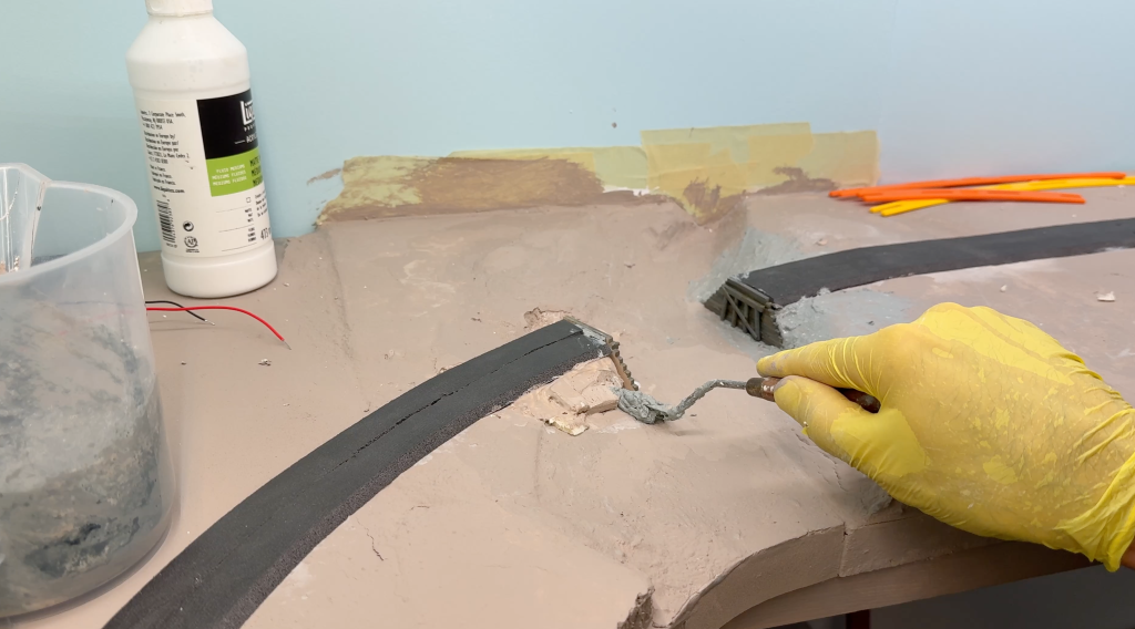
It took a couple of days for the papier-mâché to dry completely. Then, I carefully painted the whole area again with the usual tan color.
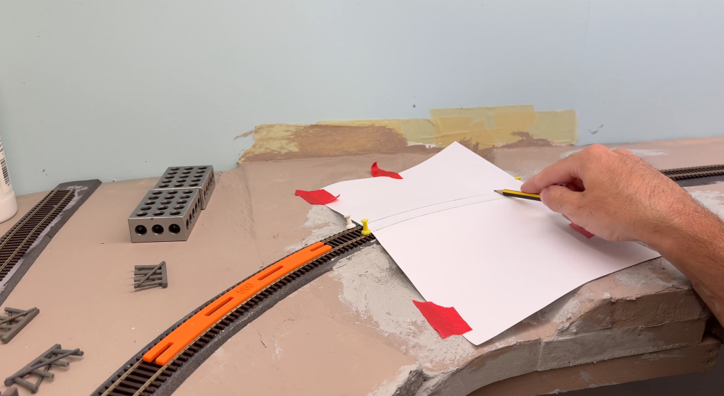
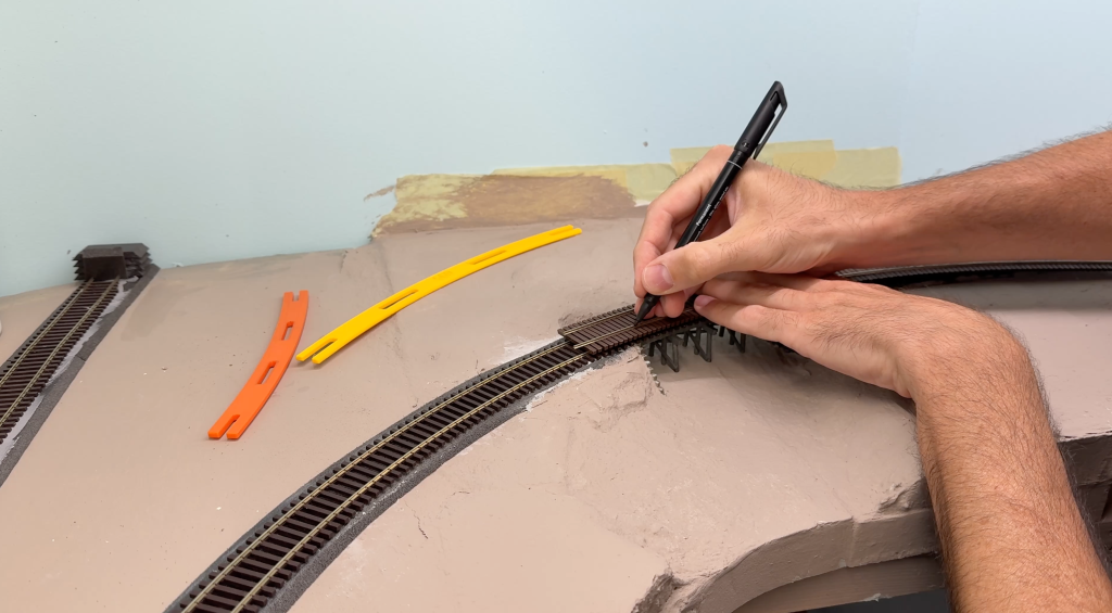
I test-fitted the track again using the curved gauge. Then, I marked the rail geometry with a pencil on a sheet of paper placed over the track. This will work as a template to glue the trestle components together.
Papier-mâché has a long working time, so there is no need to rush things here.
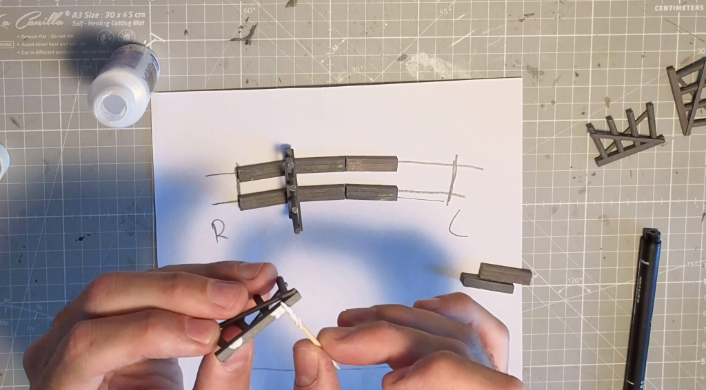
I glued the trestle components together using Microscale Krystal Klear and let it dry for 24 hours.
Before I can continue, I have to replace the Peco flex track section with Micro Engineering bridge track. I took some measurements and cut the track using the Xuron rail cutter.
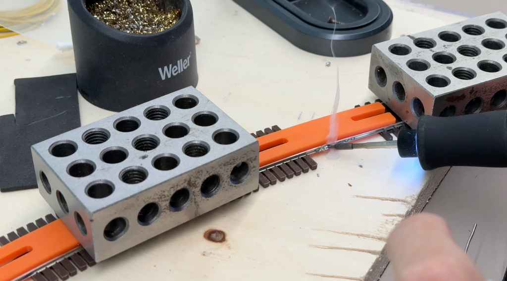
Then, I soldered the rail joiners between the Peco and Micro Engineering flex track sections to make a stronger joint.
I cleaned up the extra soldering flux with a cotton swab dipped in isopropyl alcohol.
I have a track work rule on my layouts. Each section of flex track, no matter how long it is, must have its own feeders. The bridge track is no exception. I do not rely on soldered rail joiners for electrical continuity.
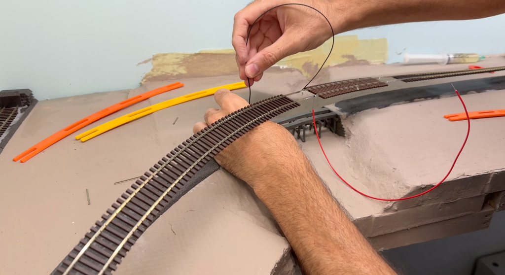
It is a little extra work, but it pays off in the long run.
I had to fine-tune the riverbed and drill holes so the bents could sit properly. Again, it is the extra effort during construction that helps avoid bad surprises later.
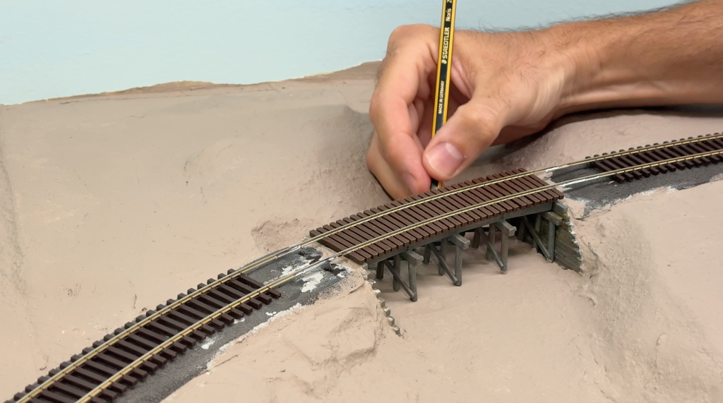
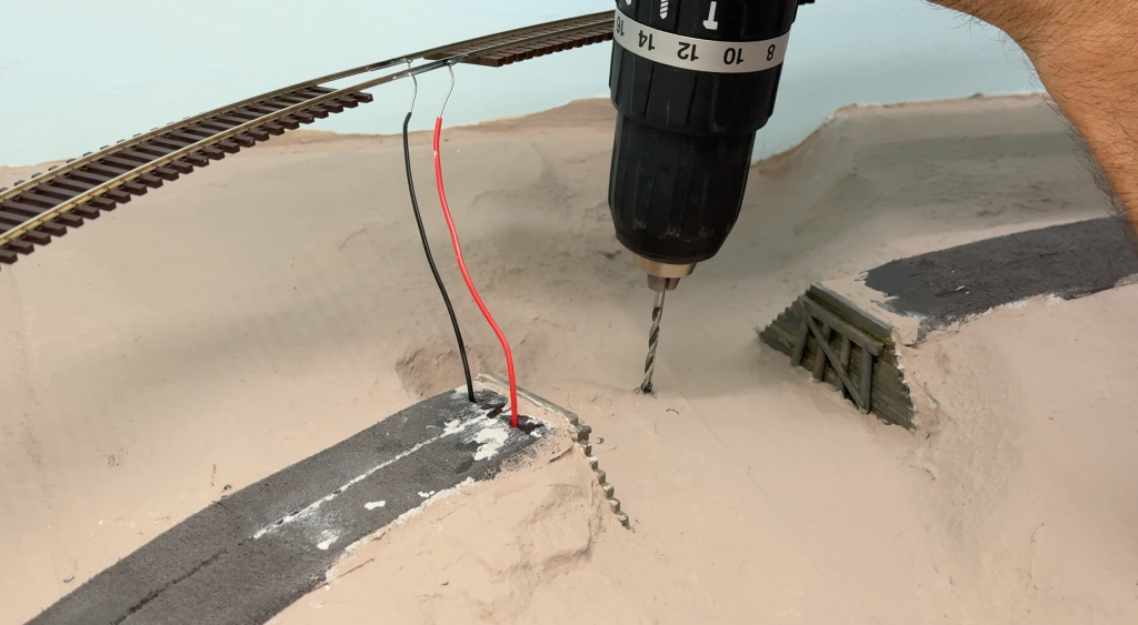
Now, the bridge sits nice and flat.
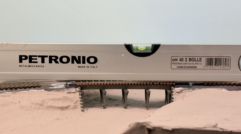
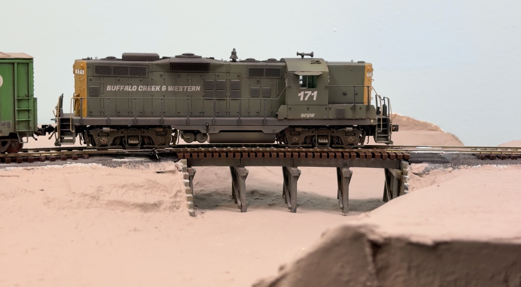
The track isn’t glued yet, but I can still test-run the first train.
The next step is adding scenery to the Buffalo Creek bridge scene.